|
This is the full text of the article submitted to Railway Modeller
and published, with a few alterations, in the April 2007 issue.
Introduction
Long ago, as a youthful reader of railway magazines, I became quite
fascinated by the idea that a model railway line could be constructed
out of doors. I can remember the precise origin of this enduring idea,
it was an article called "Tinplate in the Garden" written
by the late Jack Wheldon in the December 1968 issue of Model Railway
News. In this article Jack memorably recounted his pioneering garden
railway experiences with a collection of tinplate O gauge equipment
and the scantest of resources. Looking at the magazine all these years
later, it is strange to note that the "talking shop" section
contained the very first UK news of the LGB system of narrow gauge models
running on Gauge One track. Digressing further for a moment there were
some really good articles in that issue (edited by one John Brewer)
and a superb painting on the front cover, an atmospheric night time
view of an LSWR Beyer Peacock hauled train pausing at a snow covered
station. It was painted by a Laurie Bagley - I wonder what became of
it?
To return, as I grew up my magazine buying habit continued but as the
Model Railway News could be read for free at the local library my own
purchases tended towards the Railway Modeller. Garden railways were
at the time blossoming into what became known as Sixteen Millimetre
narrow gauge modelling and Jack's well written articles on the subject
featuring his "Border Counties Railway" (he too seemed to
have defected to the Railway Modeller) continued to inspire and inform
me. It was in one of his later articles that he introduced me to Stuart
Browne and his exotic looking Archangel models, which featured a beautiful
Prussian Blue S&DJR 0-4-4 tank in an improbably large scale called
Gauge One. Although I have subsequently modelled in various scales,
even building my own very modest contribution to the great canon of
Sixteen Millimetre modelling with the infamous "Stench Electric",
it has since that article always been in Gauge One that I have harboured
my most serious railway modelling intentions. A Gauge One garden railway
remains my ultimate railway modelling goal to this day, by which of
course you can guess that I have not yet achieved it.
Fast forward 20 years or so it was my acquisition of a house with a
big enough garden that led me to seek out and join the Gauge One Model
Railway Association (G1MRA). A vivid and still inspiring memory was
visiting my first G1MRA meeting one dark winter's afternoon in the wilds
of Northampton during 1988. A youthful looking Ken Martin was displaying
a new etched brass kit for a Southern Railway PMV and a beautiful coal
fired T9 was shooting sparks into the air - inspiration indeed. I bought
some society axle-guards and Tenmille wheels and sketched out how I
might build a tiny diesel shunter utilising some O gauge gears from
a previously unfinished project.
Unfortunately I had not planned for the various personal upheavals that
I was about to enjoy and following a move of house and loss of the "big
enough" garden I let my G1MRA membership lapse and put my Gauge
One dream to one side. Without wishing to be harsh, the quality of the
G1MRA newsletter at that time probably put the final nail in the coffin
of my then enthusiasm. Indifferently produced and containing seemingly
endless lists of who ran what in Colonel somebody's garden, it offered
little in the way of sustenance for a small scale modeller who harboured
dreams of moving up scales. I was also put off by the quality of the
Association produced axle-guards, which were not as well detailed as
those I was used to using in 4mm scale and offered no scope for springing.
I was however bitten by the Gauge One "bug", and over following
years harboured a desire to start modelling in the scale and experience
the wonders of live steam for myself.
Moving even more quickly forward another 10 years (funny how time accelerates
as you get older isn't it?) I at last found myself with equilibrium
re-established and contemplating a move of house that might just provide
a garden suitable for Gauge One railway. Whilst attending the Merstham
live steam show in the intervening years I had noticed that G1MRA had
re-vamped their quaint newsletter and were by now producing an attractive
and informative magazine in the shape of their Newsletter and Journal.
I was finally moved into re-joining G1MRA by the sight and sound of
John Barrett's Dean Goods steaming around his "Churchdean"
layout at the Llanfair garden railway show. Despite missing a safety
valve cover it looked utterly convincing at the head of its train and
made wonderful music as it clickety-clacked across the prototypically
spaced rail joints. I also found in John and his family, Lyn, Paul,
Steve and Anthony, a friendly and intelligent group of people who were
immersed in the World of Gauge One and were happy to share their knowledge
and enthusiasm with me. This time I reasoned I would make my dream come
true - even if I only achieved it by taking small steps along the way.
By this stage (2001) we had moved into a house with a garden that was
ideal for a small Gauge One layout and so I dug out the components that
I had acquired a decade earlier and took stock of my situation. With
a newly born son and another on the way (I am a late starter) I reasoned
that building an outdoor line straight away was not going to be a practical
proposition. I therefore decided to start by re-visiting my idea of
building a small diesel shunter to try out modelling in the new scale.
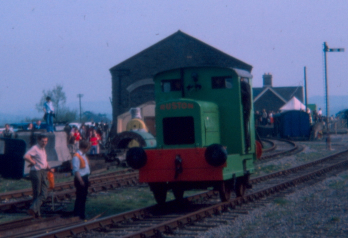
The prototype I had in mind was the diminutive Ruston and Hornsby 48DS
0-4-0, a tiny machine that I had become fond of whilst working at the
Bitton preservation project many years previously. I dug out my scale
drawing, Plastikard and assorted components and considered how to start
building.
It was at this point that I realised that Gauge One is afflicted with
its own minor scale/gauge conundrum. Whilst British Gauge One is generally
practiced at the scale of 10mm to the foot, the Gauge in use at 45mm
is correct for a scale of 1/32nd or about 9.5mm to the foot. This is
an imperial scale, exactly twice the linear size of "S" scale
and equal to 3/8th of an inch to the foot. Whilst nearly everything
that was available for British modelling in Gauge One then was pure
10mm to the foot, the thought of building from scratch to an inherently
incorrect scale seemed absurd. I decided therefore to adopt 1/32nd scale
and re-copied my scale drawings and sketches to suit. I realised that
this would put me in a minority in the UK and that I would have to work
around and adapt 10mm scale items to start off with, but after having
suffered the indignity of OO for so many years I really felt that I
had to try to get it right first time.
In any event, 1/32nd scale models and 10mm scale models are not so visually
far apart that they cannot be put together and although I would not
want to mix the two scales in my own modelling many practitioners of
Gauge One in the UK do so. The main reason for this mixing of scales
has been that Aster, a leading and popular producer of live steam Gauge
One models for the UK market, have built all of their models to a nominal
scale of 1/32nd.
Building the 48DS
Before describing how I built my model, a few notes on the prototype
may be of interest. The Ruston and Hornsby 48DS was one of the smallest
diesel powered shunters ever built in this country. Developed from a
Lister engined prototype of 1935 it was in continuous production from
1937 through to 1967 being sold to industrial users with small amounts
of rail traffic to move. My model is of the second series which was
produced from 1939 to 1949. Featuring a "key hole" steam engine
type cab this was the most numerous of the different sub series produced,
representing about one half of the complete production of 236 locomotives.
Several can be seen today, although it is sad to say that the 48DS as
a whole is a class that continues to be scrapped into "preservation"
as new owners struggle to find uses for what is a tiny locomotive. For
readers seeking more information on this fascinating subject and its
bigger brother the 88DS, I can recommend David Hall's excellent book,
The Ruston Class 48DS and 88DS Locomotives, see the end of the article
for a full reference. I note from this book that I building a model
of Works Number 232622, which was ex works to John Dickinson's paper
mills at Keynsham on 26th October 1945 and which is, I fear, currently
lying dismantled at Long Marston.
I commenced work by creating a basic box shape out of 60thou. Plastikard
to represent the locomotive's footplate. The pieces were cut out to
dimensions taken from the scale drawing, the edges of all cuts were
cleaned up with a knife edge and files to restore a regular rectangular
section and then the four sides and one top "lid" were joined
together with Mek Pak brushed along simple butt joints. I find that
the preparation of Plastikard, both in restoring edges as above but
also by gently abraiding all surfaces with fine wet and dry paper before
construction, greatly aids the formation of strong and neat joints.
The next job was to cut and shape a radiator housing, middle bonnet
section and rear fuel tank section out of 20 thou Plastikard. The radiator
housing consists of front and back pieces cut to the outline of the
casting on the drawing, with two slightly smaller pieces attached by
solvent to the insides in such a way that a rebate is formed around
the top and sides. This rebate accepts a strip of Plastikard which forms
the "skin" of the casing. For the bonnet assembly proper I
adopted a similar approach but with the shaping pieces (all of which
are covered by the bodywork) being attached to each other by means of
an internal cruciform box construction of Plastikard. The final fuel
tank section was constructed in the same way as the radiator housing.
Radiator and fuel filler caps were filed to shape from scrap plastic
sprue of suitable diameter from the scrapbox and Mek-packed into slight
holes formed in the bodywork in order to ensure a secure fit. The radiator
grille on my model is automotive aluminium repair mesh from Halfords
although it should be a finer grade to be strictly accurate to the prototype.
The correct shapes of the radiator and fuel tanks in particular were
finally achieved by the addition and filing back of small amounts of
Humbrol model filler. This was done in order to lose some slight joint
marks but also to adjust the radius of the finished articles so that
they best matched the scale drawing when placed upon it. I should say
at this point that the scale drawing I worked from is in Eric Tonks'
book Ruston and Hornsby locomotives.
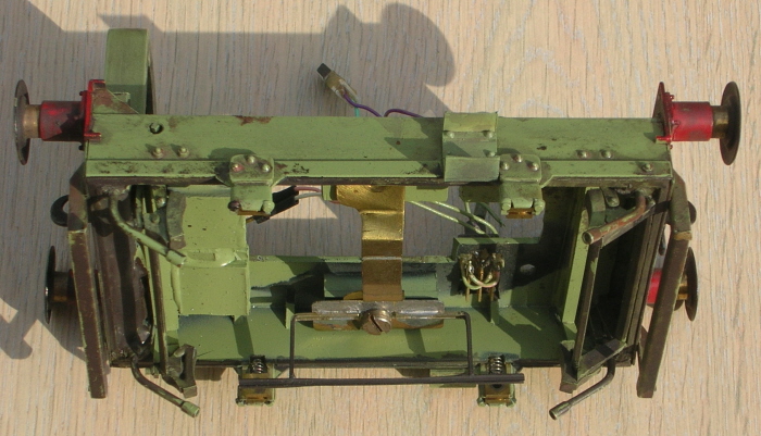
With the body taking shape, I turned my thoughts to how to build the
chassis. The prototype has small outside bearings that are cleverly
bolted to horizontal bar frames welded to the locomotive's outer frames
in such a way that the wheelbase is adjustable in order to take up the
slack in the drive chains. Whilst I didn't intend to replicate this
clever feature I decided that working outside bearings were a practical
proposition in Gauge One and taking my Tenmille wheels looked at the
outer ends of their axles to decide how best to achieve this. The wheels
I had bought were 24mm diameter disc wheels, which (unlike most Gauge
One wheels which have a relatively large journal diameter of 1/8th of
an inch) had journal ends of a mere 2mm diameter. Looking through my
4mm parts, I found a pack of Alan Gibson sprung hornblocks for 2mm axles
(Gibson part reference 4M61) which would fit perfectly on the ends of
the Tenmille axles. I cut out two pieces of brass sheet with my piercing
saw to represent the locomotive's two lower frame sections, with a slot
and protruding "legs" in each of the four axle box positions.
I then cut out four inverted U pieces of brass whose internal space
provided a running fit for the Gibson hornblocks. By carefully soldering
these behind the main frames in each axle box position I effectively
formed correctly spaced hornblock guides built in to the horizontal
frame pieces. The only parts of the Gibson kit I actually used were
the four milled hornblocks themselves, springing is provided by directly
epoxying cut in half springs from Smiths 4mm scale coupling packs to
their top edges. Hopefully the accompanying pictures will help to show
how this all fits together on the finished model.
Having created these two chassis pieces and tested the operation of
the assembled Gibson hornblocks in them, the next job was to stick them
to the outside of my Plastikard chassis box to create a rolling chassis.
Before this could be done I had to scrape out four recesses in the surface
of the Plastikard footplate to accommodate the sides of the brass hornblock
guides described above, together with a slight cut out in the lower
edge at these points to locate the springs stuck to the tops of the
Gibson axleboxes. This I did with 5 minute epoxy resin, after first
abraiding both the brass and Plastikard surfaces that were to be joined
in order to give the resin a good "key". With the bonnet assembly
placed on to the chassis box and with the wheels temporarily fitted
with their sprung hornblocks, the whole project started to look like
a potentially viable railway vehicle rather than an unlikely collection
of mis-matched parts.
Although the prototype is driven on both axles I decided to power my
model on only one axle, reasoning that the simplicity of such an arrangement
meant that I might get the model running before I ran out of enthusiasm
and also that suitable weighting of the finished model would give the
model a hauling power which would at least equal its prototype performance.
Taking the brass gear wheel and steel worm that I had bought 25 years
or so before from Home of O Gauge in Raynes Park, I was pleased to find
that the gear was a perfect fit on to the Tenmille axle. I was using
a cheap 1.5 volt motor whose shaft was too small for the worm, but my
friend Brian Clarke very kindly turned me up a brass sleeve that enabled
the worm to fit my motor. I made myself a simple gearbox out of brass
sheet and Brian turned me up some "top hat" bearings and spacers
of appropriate width so that I could hang the motor on the axle, which
arrangement means that the locomotive has working suspension on all
wheels. If you wanted to build this model for 2 rail operation (I was
at this point aiming at battery operation with this model) then you
could use one of the very many motor gearbox combinations for small
O gauge locomotives instead of my somewhat homespun arrangement.
The next step was to make a cut out in the Plastikard footplate that
would clear the motor. With the motor and gearbox assembled on to the
axle and aiming for a horizontal position when finally assembled only
a relatively small cut out was required. This was hidden by the bonnet
assembly later on and the motor sat satisfyingly low in the chassis
with only its upper surface rising above footplate level. Suitably encouraged
I continued to cut out various thicknesses of Plastikard which I then
cut, shaped, glued, filled and filed to produce front and rear buffer
beams, sandboxes, axleboxes, side steps, cab pieces and sundry other
fittings.
It is at this point that you realise that the 48DS is a modeller's dream
because of its extreme simplicity and lack of embellishment. Nearly
all of the loco consists of simple shapes that are easy to create in
Plastikard, making this an ideal beginners project in Gauge One. Also
the tiny size of the loco which makes it such a challenge to recreate
in the smaller scales is a positive advantage in Gauge One, the pieces
you are creating and working with are not enormously large and familiar
small scale modelling techniques and materials can be employed throughout.
Having said that there were a few parts of the model that I found quite
challenging and which required slightly different approaches to those
with which I was familiar. The most difficult of these was the recreation
of the louvres on the bonnet side. On my original model they were rather
crudely made by cutting slits in Tomato Puree tube metal in rows which
I then lifted out with a knife blade to create the louvre shape before
sticking down onto thin Plastikard which was in turn attached to the
bonnet sides. I was never happy with the result and I have since got
Fred Phipps (of Caradoc Models) to make me some superb patterns in Milliput
which I took a mould of in Silicone rubber and cast in Polyeurethane
resin. I got Fred to do this as part of an idea to produce this loco
a kit, which I am still hoping to do at some point in the future. If
anyone wishes to build one of these models in 1/32 scale for themselves
in the meantime I would be happy to cast them some resin louvre sections
in resin for a few pounds. Contact me via the editor if you are interested.
The loco pictured with this article has the resin louvres fitted to
it.
As noted previously the cab side sheets on the version that I built
have a steam locomotive style "key hole" cab door (later versions
had an enclosed cab with glazed doors and windows), which has a beading
attached to its edge. This is actually formed from a squashed tube section
on the prototype which follows the outline of the cab opening. After
various experiments I eventually cut the beading out of 10 thou Plastikard
as one single piece, oversize to the door opening by just over 1 millimetre
- the amount of beading I wanted to show. I then laid it over the door
opening and marked out the line for cutting out a single beading shaped
strip of Plastikard by drawing around the door opening. I cut this out
with a knife and used a file to improve the shape before gluing around
the cab openings with Mek Pak applied sparingly from a fine brush. Once
the beading had set, I then chivvied at it with knife blade, file and
fine wet and dry paper in order to suggest a half round section. This
wasn't as tricky as it sounds and yielded a result with which I am happy,
like much in modelling it is an operation where it pays to take your
time and use a sharp blade.
The cab roof was a similar challenge to the cab sides in that there
is a continuous strip of beading around its edges. First though, the
shape is required to be formed and in order to give a strong job and
achieve the tight radius over the cab openings of the prototype I decide
to make this out of a piece of brass sheet. I used a piece of 20 thou
sheet from the K&S range that I had in stock but before cutting
it made a paper pattern to work out the exact shape and size that was
required. Having marked the brass with a scriber drawn around the pattern
I then cut the shape out with my piercing saw. Once I had got the correct
shape I annealed the brass by heating it up to cherry red heat with
a small blowtorch, when it had cooled it was very easy to bend to shape
to follow the outline of the cab. I can't remember exactly how I did
this, I think I bent it around a piece of smallish diameter wooden dowel,
but whatever I did it wasn't difficult and I achieved the right shape
at my first attempt - much to my surprise. In order to achieve the look
of the beading, I cut Tomato Puree tube metal into thin strips that
looked about right and superglued them to the edge of the cab roof.
I then cut some brass strengthening brass ribs and epoxied them to the
underside of the roof, these are not visible from normal viewing angles
when the roof is placed on the cab.
The final part of the locomotive where I resorted to serious help was
the buffers. My friend Brian again came to my rescue by turning me up
a superb set of buffer casings and shanks, based upon a detailed examination
and measurement of a spare set that are still mouldering in the yard
at Bitton alongside the remains of a second 48DS chassis. The over large
buffer heads which are such an endearing feature of small industrial
locomotives I cut out of brass sheet with the trusty piercing saw. After
fettling with a file and fine wet and dry paper to get a more or less
round shape and lose the burrs from cutting out, I gently hammered the
resulting discs with the round end of a small ball pein hammer against
a block of soft wood to achieve the characteristic dished appearance
of the prototype. In service these oversize buffer heads invariably
got bashed about and so it doesn't matter if your buffer heads acquire
a few dents or ripples during this process. These oversize heads were
then epoxied on to the turned brass items that Brian had made me. I
drilled out the buffer base-plates in each of their four corners where
the attaching bolts are fitted on the prototype and then using each
as a template held against the Plastikard buffer beam drilled through
each hole in turn. This was to ensure that each buffer housing fitted
on to the locomotive neatly and in the correct place. A better modeller
would have done it all by accurate measurement and marking out but I
know my limitations! The buffers were attached to the loco by means
of pieces of paper clip wire cut to short lengths to represent bolts
being inserted through each hole with the whole being super-glued to
the buffer beam. My buffers operate exactly as the originals with the
rear of the centre bosses moving through a hole in the buffer beam.
If you had to modify a commercially produced sprung buffer as an alternative
to my bespoke solution then this would be a useful feature I think.
Looking at the side of the prototype, at the front a strengthening fillet
and the sandbox effectively mask the rear of the buffer whilst at the
back the whole area is inside the cab.
At this stage I started to think about how to control the locomotive
and responding to an advert in the G1MRA newsletter ordered one of Peter
Spoerer's "Electro Reg" units, advertised as being suitable
for operation of low voltage motors. I built the circuit as instructed
but used a small pre-set potentiometer in place of the variable potentiometer
supplied (but with the same values) as this meant that I could build
a small regulator unit into the dashboard of the model. I also substituted
miniature toggle switches as isolating and polarity reversing switches
for those supplied as I again wanted to build these in to the cab as
semi-scale operating levers.
The circuit board I buried into the bonnet structure, connected to the
pre-set and and switches by small connectors and flying leads. As the
motor was a 1.5 volt one I thought I would drive it from 3.0 volts supplied
by two penlight batteries, which is just about all that can be fitted
behind the cab side sheets. I built it all and connected it up and turned
the unit on in eager anticipation of my first Gauge One locomotion.
Disappointingly, nothing happened so suspecting my soldering I checked
all my joints, re-made a couple and tried gain - nothing. Not being
an electronics whiz but still being in possession of a parent who is,
I passed the apparently defunct circuit over with a request to "sort
it out". Several unpleasant smelling cigars and a telephone call
to Peter Spoerer later the offending article was returned, with the
news that the circuit was functioning correctly but that I was not putting
enough volts through it to make it work. I found that by connecting
a PP9 to the input I then got a satisfactory result, although battery
life was less than really useful. I also noticed that the battery got
very hot while driving the circuit and came to the conclusion that there
was something very inefficient happening. Moving some months and several
PP9s later on, I eventually replaced the whole circuit with a very neat
one being sold at the Merstham steam show by Chris Mackenzie of "Timpdon
Sheds Open Day" fame. The circuit used is the "Speedcon SC1"
which is still available from Chris through his Timpdon Electronics
offshoot. It is a clever piece of microprocessor based circuitry that
works very happily off two 1.5 volt penlight batteries which also last
a satisfyingly long time in service. To be fair to Peter Spoerer I suspect
that his circuit would perform much better if it were controlling a
motor which required a higher voltage where all the volts weren't being
dropped across the circuit.
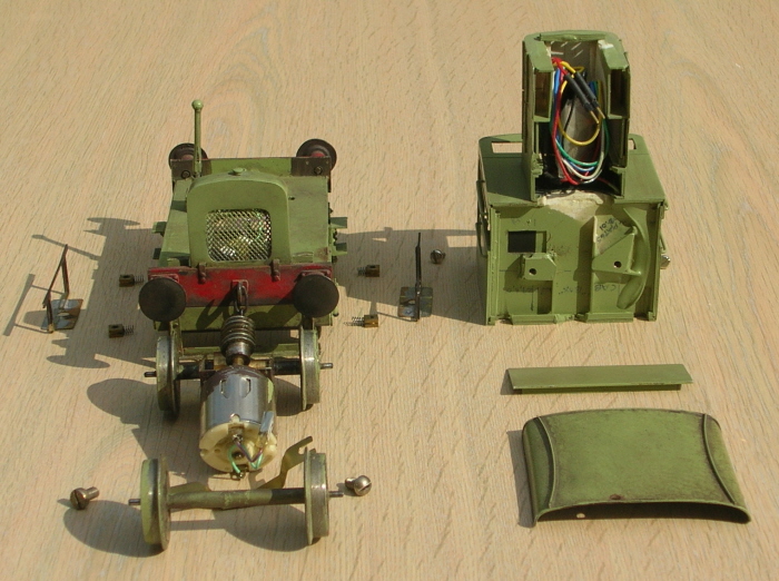
With all the main body components now fabricated and with the control
circuit in place, I next turned my attention to sticking all the pieces
together in such a way that the loco could be broken down into separate
units for painting and subsequent maintenance. This is an important
area of model construction as it is almost inevitable that your pride
and joy will require attention of some sort after you have finished
it, just as mine did with the electronic heart transplant described
above. The method I decided upon was to split the basic body into two
sub assemblies. The complete footplate was fixed to the front radiator
casting to form one unit whilst the bonnet and fuel tank were fixed
to each other and then firmly welded to the cab with Mek-Pak to form
the second. The bonnet and cab assembly engages with the radiator by
means of a simple Plastikard tab and is firmly attached to the footplate
beneath the cab floor by means of two bolts which go through holes in
the footplate and engage with captive nuts epoxied below a false cab
floor. Hopefully the photographs will show this more clearly than I
have described it. As noted previously, small electrical connectors
were used to separate the wiring loom at various key points.
Having built the basic locomotive I next set about adding the relatively
few small details that adorn the original. The exhaust pipe is a piece
of brass tube with a piece of brass wire curved around it and soldered
on forming the fixing bracket. This wire projects into the cab by a
small amount through a strategically drilled hole and is secured in
place by a blob of epoxy inside the cab. Each of the four axleboxes
were carved out of Plastikard which had been fabricated into a shallow
box which fitted around and over the hornblock/guide assemblies in such
a way that movement was still possible. For recreating the heavy rivet
heads and bolts on the bottom corners of the axleboxes I used parts
from the versatile Cambrian rivet and nuts and bolts mouldings. Although
designed for 16mm modelling I find these mouldings very useful for building
1/32 stock and as the photographs show I was able to use these to represent
most of the bolt and rivet heads on the 48DS. Lamp brackets were fabricated
out of Plastikard, I chickened out of making the lamps although I guess
they could be made working in this scale. From photographs of the prototype
however they were often missing from the locomotives when they were
in service.
Having assembled the loco the final step was to fabricate the brake
gear, which I did from various strips and blocks of the ever versatile
Plastikard plus odd bits of sprue from the scrapbox. The sandpipes were
made from copper earth wire with small pieces of brass tube soldered
to the ends to replicate the look of the originals. These swivel in
the holes into which they are planted in order to allow the wheels to
be removeable. Cab handrails were simply bent up from brass wire and
epoxied into holes drilled into the cab sides with a pin vice. Re-railing
bars were assembled from brass angle and epoxied to the front and rear
of the chassis.
The penultimate parts of the jigsaw were to devise the brackets required
to retain the wheels in the chassis and hold the motor in place and
horizontal inside the chassis. I built two Plastikard boxes on each
side of the underside of the footplate which contained captive nuts,
secured by epoxy and a Plastikard "lid". Secured to these
by matching bolts are brackets made up of brass sheet and old code 75
nickel silver rail in the shape that is shown in the accompanying photograph
(I can't think of any sensible way to describe the shape in words).
These serve to hold the axles in place and are built so that when the
loco sits on its own weight the axles rise clear of the retaining strip
of rail. I filed this flat and painted it dark brown reasoning that
it would then look like a piece of drive chain or something similar
when seen under the finished locomotive. The motor is supported in a
horizontal position by a shaped brass "saddle" which is slotted
at each end so that it is held by the bolts attaching the two brackets
described above to the captive nuts inside the Plastikard boxes. Again
I hope that the photographs illustrate this arrangement better than
I have described it. The final piece of construction was the epoxying
of as many pieces of cut up roofing lead under the chassis as I could
fit in, making the whole thing slightly front heavy so that when the
batteries were loaded in the cab the locomotive sat level.
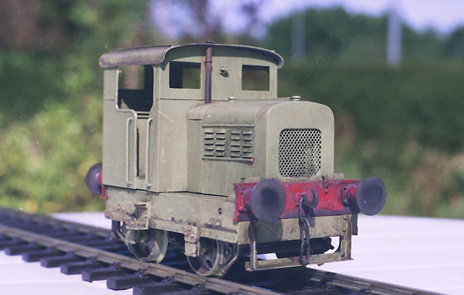
After separating the parts of the finished structure into its constituent
parts I masked the axle ends, hornguides and electrical connectors with
Tamiya masking tape. This has much less tack than regular masking tape
and is very easy to use. I first primed the whole model with Grey primer
in an aerosol from Halfords, taking care to try and give thin coats
and spray each piece from different angles and using a collection of
clothes pegs and baby-food tins and jars to support each item in turn.
Once this was dry I sprayed each piece with the final coat of Halfords
"Vauxhall Reed Green" as I thought this best represented the
loco as I first remembered seeing it parked on its siding alongside
the main line outside Keynsham Station.
Once the paint was dry I removed the masking tape, put the locomotive
together again, and admired my handiwork - at last I had finished a
model. Initial pleasure was somewhat tempered when I painted the buffer
beams red, despite my best efforts the finish was over bright and slightly
patchy looking. I painted the buffer heads with metalcote gunmetal let
down with some rust colour. The metalcote gives a pleasing metallic
finish when it is subsequently polished, which I did in the centre of
the buffer heads.
With reference to Martyn Welch's excellent book The Art of Weathering
I mixed up a wash of metalcote gunmetal, matt grey and matt leather
and attempted to copy the master with a paintbrush rather than airbrush
(I haven't taken enough "brave pills" to attempt airbrushing
yet). Despite the lack of an airbrush I was pleased with the results,
mainly because of an accidental effect whereby the weathering wash settled
in to a very slight orange peel finish which my inexpert spraying had
imparted to the surface of the model. I highlighted various parts of
the resulting finish with a mix of rust and grey paint, then used a
thinned mix of the original weathering concoction to feather in and
merge these areas with the rest of the model whilst also further weathering
areas like the brake rigging and lower parts of the buffer beams and
chassis. At the end of this process I was quite pleased with the results,
and took the finished model out in to the garden to take some photographs.
Conclusions
The loco first ran on a Gauge One layout when it did a few test circuits
of John Barrett's "Midsomer Norton" at Camrail in 2002 before
the show opened. Since then I have taken it to a few other Gauge One
layouts but it hasn't proved suited to main line running and would be
happier shunting a few wagons around a small yard. I therefore cast
around for a suitable wagon for my completed loco to shunt and as I
had decided to model in 1/32nd scale this meant scratch building again.
With the editor's permission I will describe building my first wagons
and continue the story of how I started in Gauge One in a further article.
At this stage I can confidently report that 1/32nd is a most satisfying
scale in which to model. It is small enough to enable you to use all
of the materials and techniques that you picked up in 4mm or 7mm scales
whilst the resulting models have a presence and mass that is simply
unachievable in smaller scales. I find that the challenge is in modelling
sufficient fine detail to make sure that the finished model looks convincing,
there is less scope for "fudging" and suggestion than there
is in the smaller scales.
I can also report a definite growth of interest in Gauge One modelling
at 1/32nd scale amongst erstwhile small scale modellers since I started
out. It would also appear that 1/32nd scale is increasingly becoming
the more general choice in Gauge One with Bachmann recently moving into
the market with ready to run 1/32 brass locomotives and Slater's now
producing all their new Gauge One products to 1/32nd scale only. Simon
Dunkley and myself have developed a new set of track and wheel standards
called "ScaleOne32" and are working on the development of
several new products that will directly support a finescale 1/32nd approach
to Gauge One modelling - the future looks bright indeed. Oh and by the
way I still haven't started my garden layout - yet!
References
Castens, Simon, 1/32nd Modelling Resource Centre, http://titfield.co.uk/Modindex.htm,
Website.
Hall, David R. The Ruston Class 48DS & 88DS Locomotives, Moseley
Railway Trust, 2003, ISBN 0954087844. Available.
Tonks, E. S. Ruston & Hornsby Locomotives, Industrial Railway Society,
1989, ISBN 0901096210. Out of print.
Welch, Martyn, The Art of Weathering, Wild Swan Publications, 1993,
ISBN 1874103119. Available.
|